
Page 103 - Vauxhall 20-60 H.P. (R Type) Chassis Shop Manual
P. 103
VAUXHALL 20-60 SHOP MANUAL
On cars bearing chassis number prior to R 1833 the timing chain is supplied with
oil through a pipe connected to the crankcase below the oil relief valve, and on
cars bearing chassis number R 1833 and onwards the timing chain is lubricated
from the front camshaft bearing supply. Another supply pipe from the pump
carries oil under pressure through the oil filter mounted on the induction
side of the engine, to the centre of the hollow rocker spindle from which it is
distributed to the rocker bearings and the ball ends of the push rods.
The oil returns to the sump through tubes which encircle the push rods,
thus giving ample lubrication to the tappets and cams as it flows down.
An oil gauge mounted in the instrument panel registers the pressure existing
in the engine lubricating system, the reading varying with engine speed and
temperature. In no circumstances must the gauge register less than 1 lb. per sq.
in. when the engine is ‘ticking over’ when hot, the pressure rising rapidly as the
engine speed increases giving a minimum reading of 15 lbs. per sq. in. at 30 m.p.h.
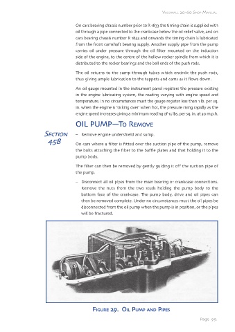
OIL PUMP—TO REMOVE
SECTION – Remove engine undershield and sump.
458 On cars where a filter is fitted over the suction pipe of the pump, remove
the bolts attaching the filter to the baffle plates and that holding it to the
pump body.
The filter can then be removed by gently guiding it off the suction pipe of
the pump.
– Disconnect all oil pipes from the main bearing or crankcase connections.
Remove the nuts from the two studs holding the pump body to the
bottom face of the crankcase. The pump body, drive and oil pipes can
then be removed complete. Under no circumstances must the oil pipes be
disconnected from the oil pump when the pump is in position, or the pipes
will be fractured.
FIGURE 29. OIL PUMP AND PIPES
Page 99.